Basic Information
Instructor: Michael Heilemann
Office: CSB 611
Hours: F, 12:00 PM
TA: Aaron Bundy
Office: CSB 412
Recitation: M, 3:25 PM in CSB 523
TA: Ben Thompson
Office: CSB 412
Recitation: W, 1:15 PM in CSB 601
TA: Yunji Kim
Simple Harmonic Oscillator Response Phasor Plots
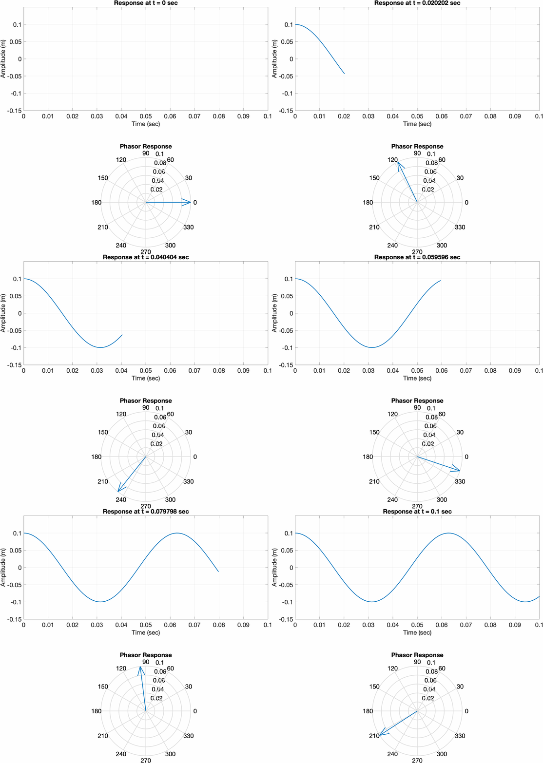
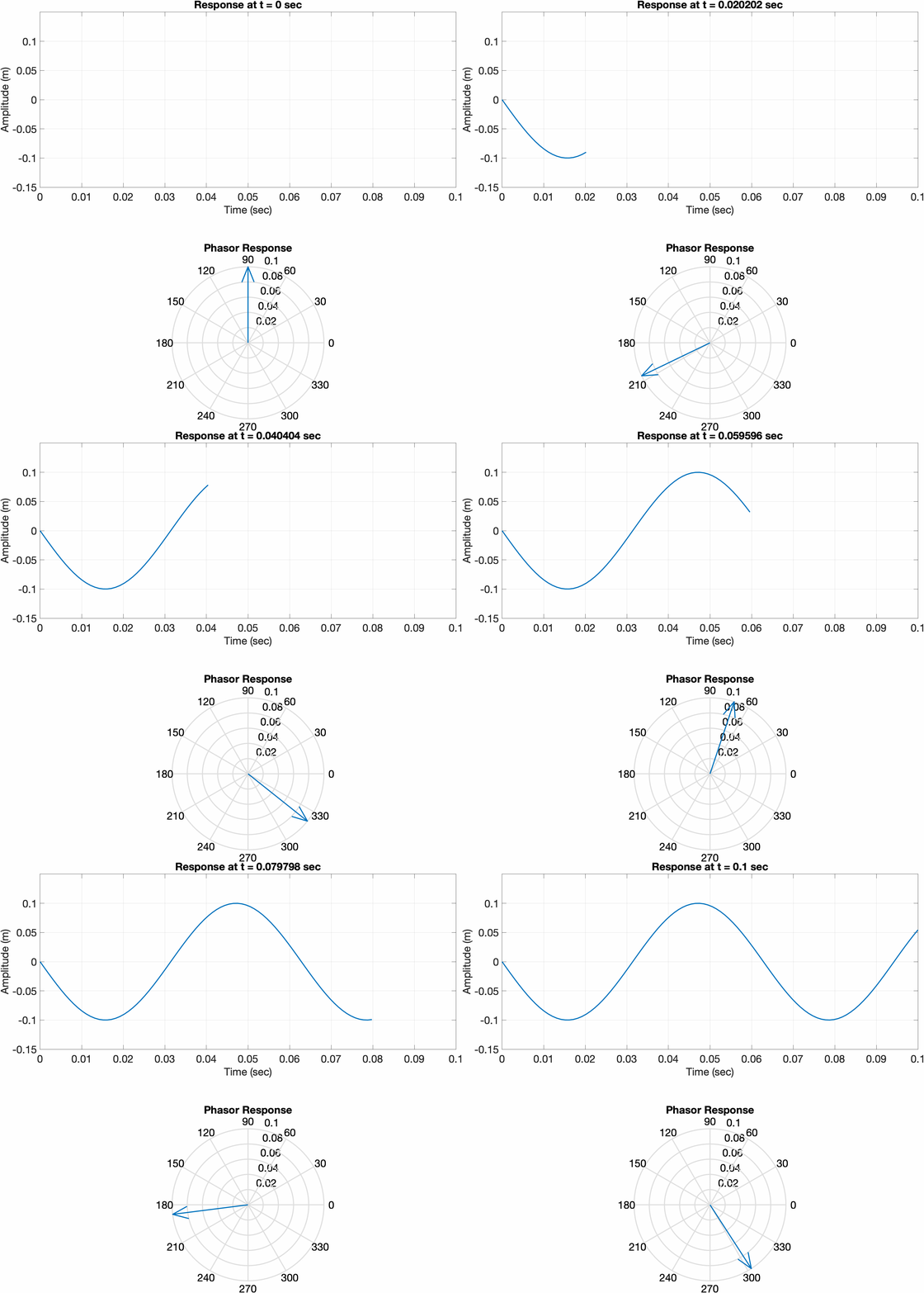
Since the initial conditions of a simple harmonic oscillator system are real, the solution must also be real. If we solve the equation of motion using complex exponentials, the response of the system my be determined by taking the real part. Consider a mass-spring system, with two different sets of initial conditions. The first is displaced a certain amount and released from rest, while the second is initially at rest and given an initial velocity. Notice how the phase vector for the first system initially points along 0 degrees, meaning the real part of the response is at its maximum. In the second plot, the phasor is initially pointed at 90 degrees, meaning the real part of the response is at 0.
Traveling Waves on a String
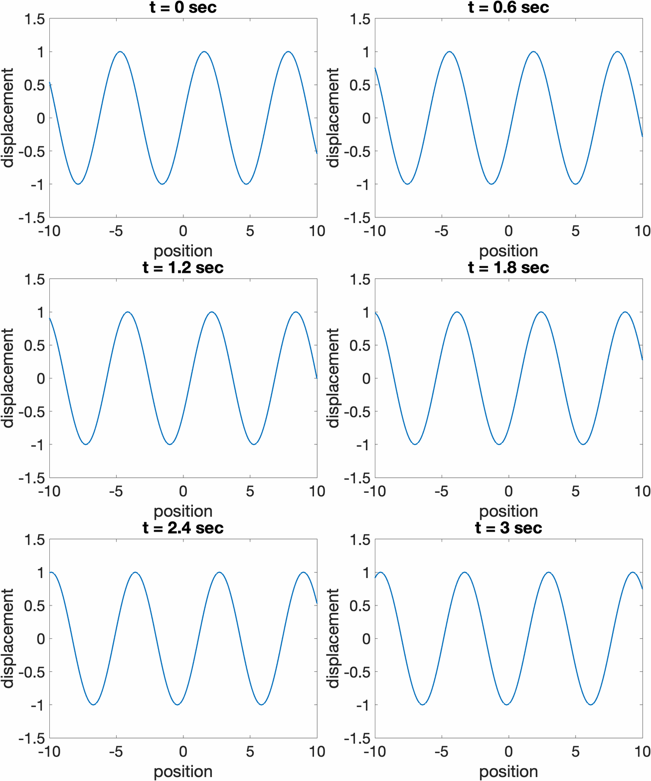
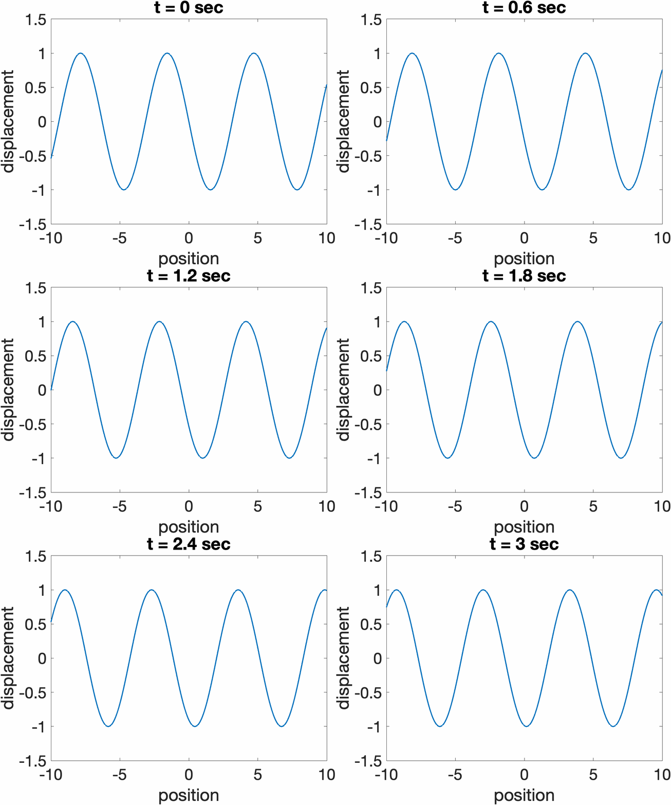
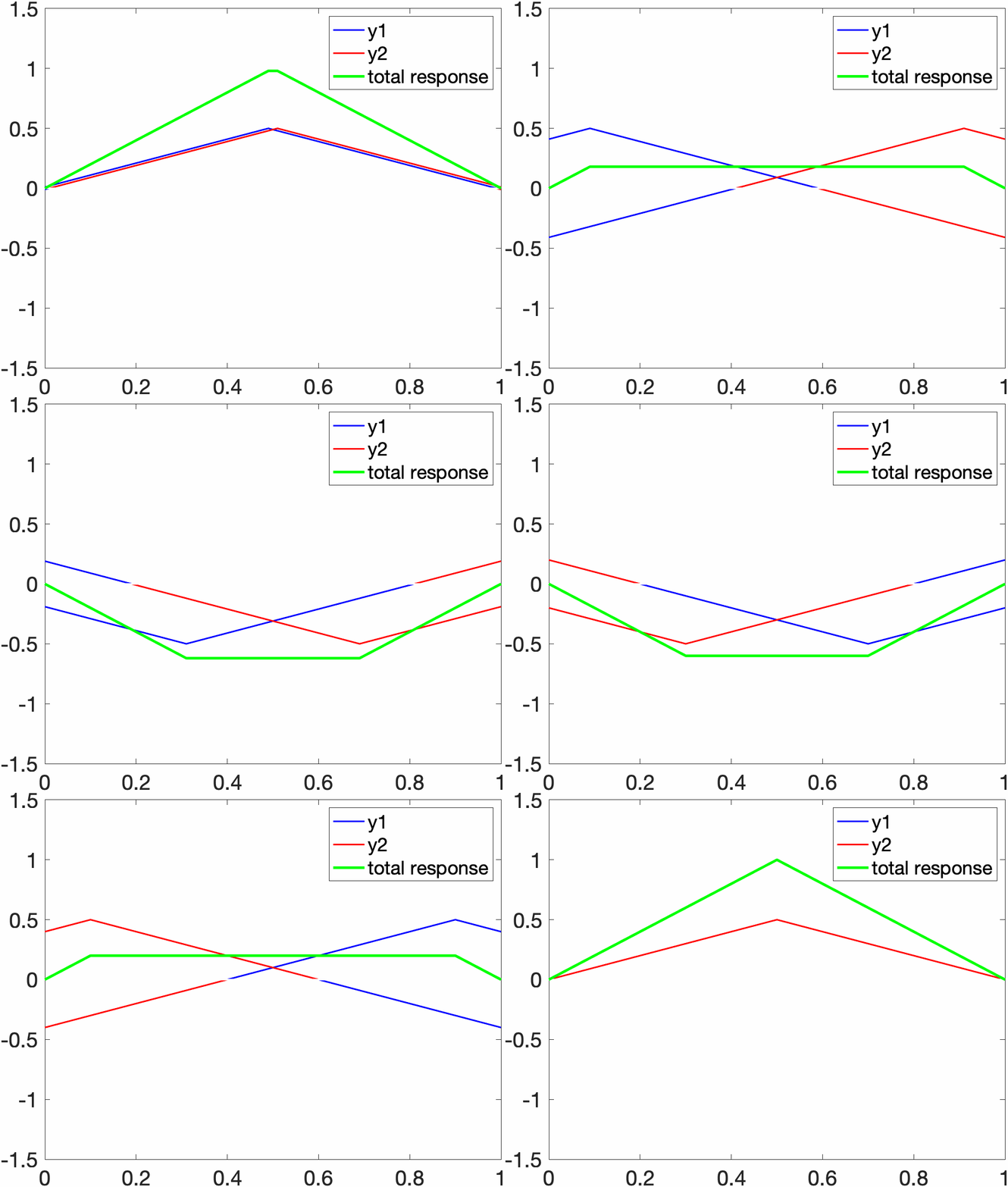
The total response of a string y(x,t) can always be expressed as a sum of two traveling wave functions traveling in opposite directions, y1(ct + x) + y2(ct - x). Examples are shown below for a sine wave propagating to the left (ct + x), and right (ct. - x)
Resonant Modes on a String
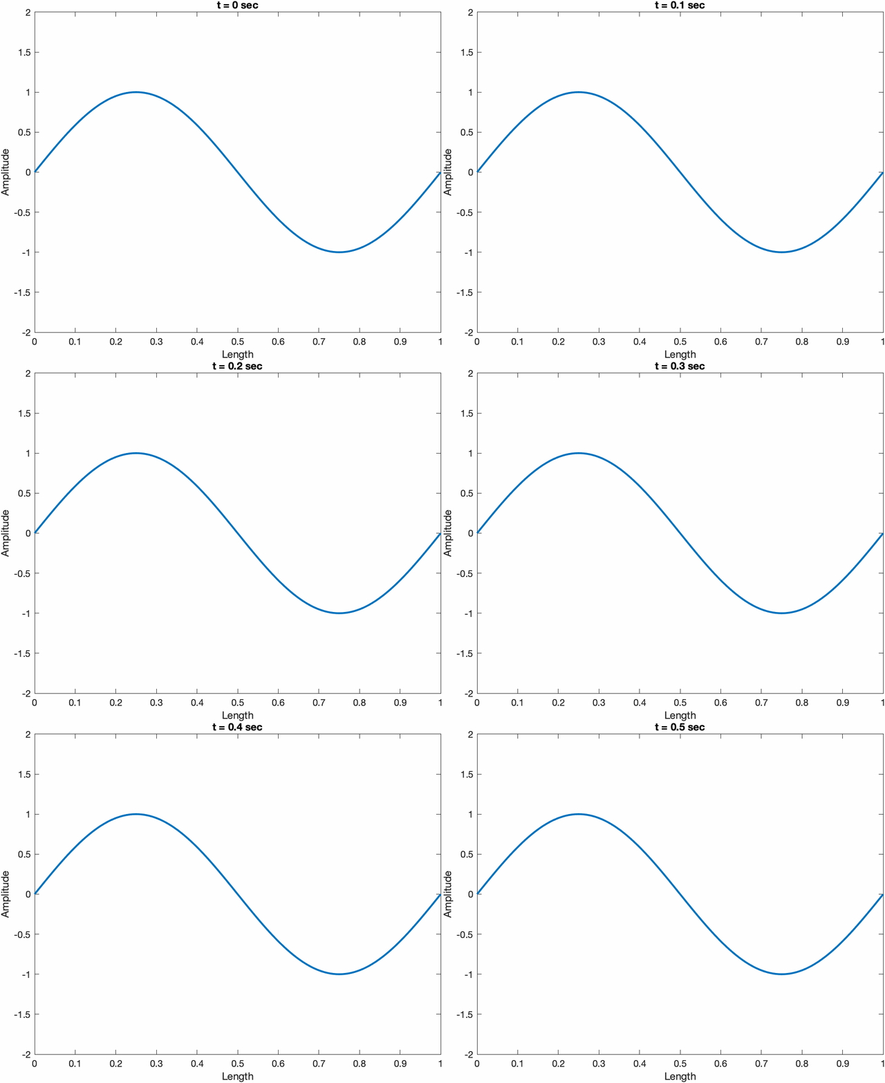
In addition to the traveling wave solution, the total response of a fixed-fixed string ỹ(x,t) of length L can also be expressed as a superposition of resonant modes. The response of each mode ỹn(x,t)=Ãnsin(knx)e jωnt. The boundary conditions force each mode to have a wavenumber kn proportional to an integer multiple of π divided by the length of the string (nπ/L). Each mode will oscillate at a frequency ωn = knc. Notice below how the n = 1 mode has one spatial half-wavelength, while the n = 2 mode has two spatial half-wavelengths. The n = 2 mode oscillates at twice the rate as the n = 1 mode. The amplitude Ãn is determined by the initial conditions.
The amplitude of each mode is determined by the initial conditions of the string. In the case below, the string is lifted in the middle, and released from rest. You can determine how much each mode contributes to the overall response by integrating the product of the mode shape and the initial displacement over the length of the string. Notice below that the even modes do not contribute to the overall response due to the symmetry about the initial pluck point. Each mode evolves over time at it's own frequency, and gives the same solution as the superposition of two traveling waves moving in opposite directions and reflecting off of the fixed ends (shown below).
An electric guitar uses a transducer called a “pickup” that generates an electric signal based on the motion of the string. The pickup consists of a series of magnets wrapped by a coil of wire. The motion of the guitar string alters the magnetic field, which induces a current in the wire. The resulting tone is affected by the pickup position under the string. If the pickup is near the antinode of a particular mode, it will “hear” that mode with the amplitude it is excited. If the pickup is near the node of a mode, it will not “hear” that mode, even if it is excited. For example, if a string is plucked near the edge so that all of the modes n = 1:10 are excited with a non-zero amplitude, the tone recorded by a pickup placed in the middle of the string will not be comprised of any of the even-ordered modes since that pickup location is on a node for those modes. The bridge pickup of a guitar is located closer to the end of the string and produces brighter tones, while the neck pickup of the guitar is located further from the end, and produces darker tones. An example is shown in the video below.
Membranes
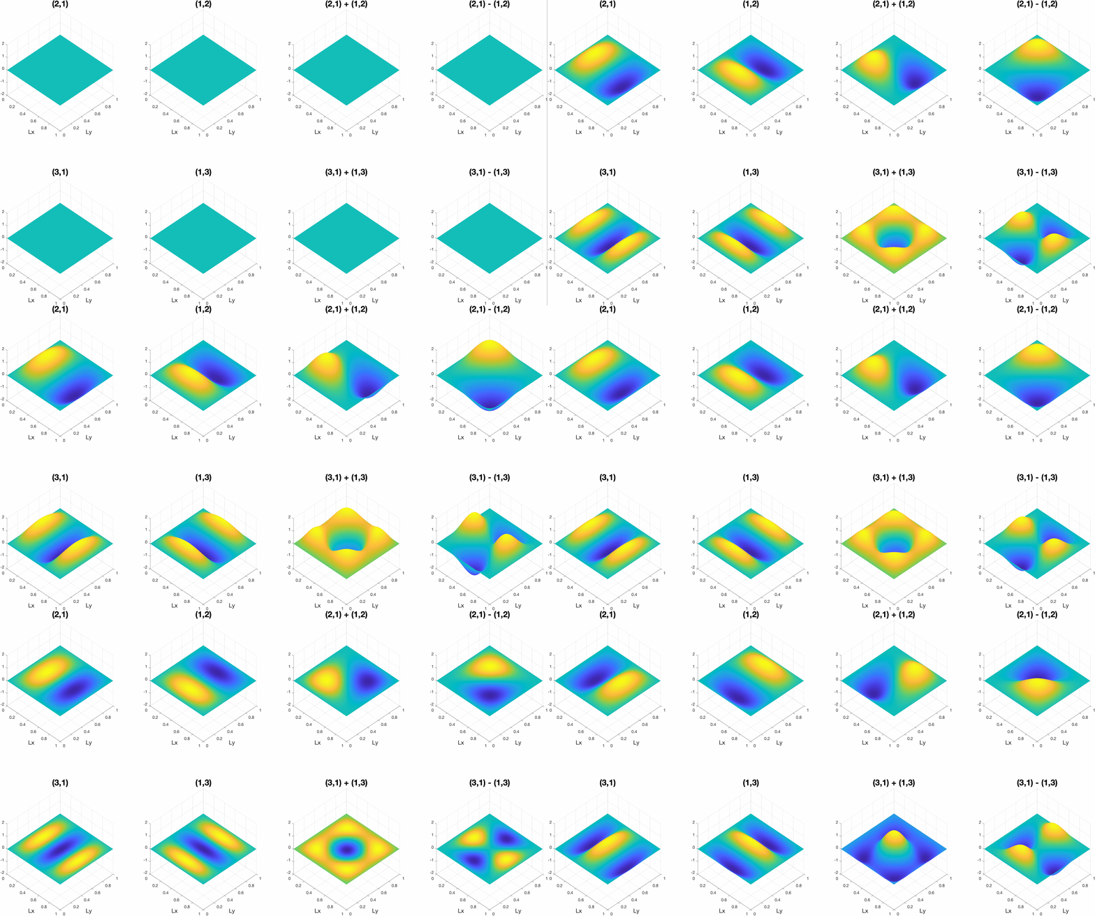
Membranes work under the same principles as strings, though wave motion now occurs in two dimensions (x,y) giving the out-of-plane displacement z(x,y,t). If the membrane is rectangular with dimensions (Lx, Ly) and fixed edges, the mode shapes (m,n) are determined by the number of half-sinusoids in each dimension as shown in the figure below. The frequencies of these modes are given by ωmn = c{(mπ/Lx)2 + (nπ/Ly)2)}1/2. This implies that the order of the resonances will vary based on the dimensions of the panel, and two modes can even have the same resonant frequency. Modes that have the same frequency are called "degenerate" modes, and the total response is given by the superposition of the degenerate mode shapes as shown in the animation below.


